
MCC and PLC Panels: Why Most Plants Have Both But Very Few Integrate Them Correctly
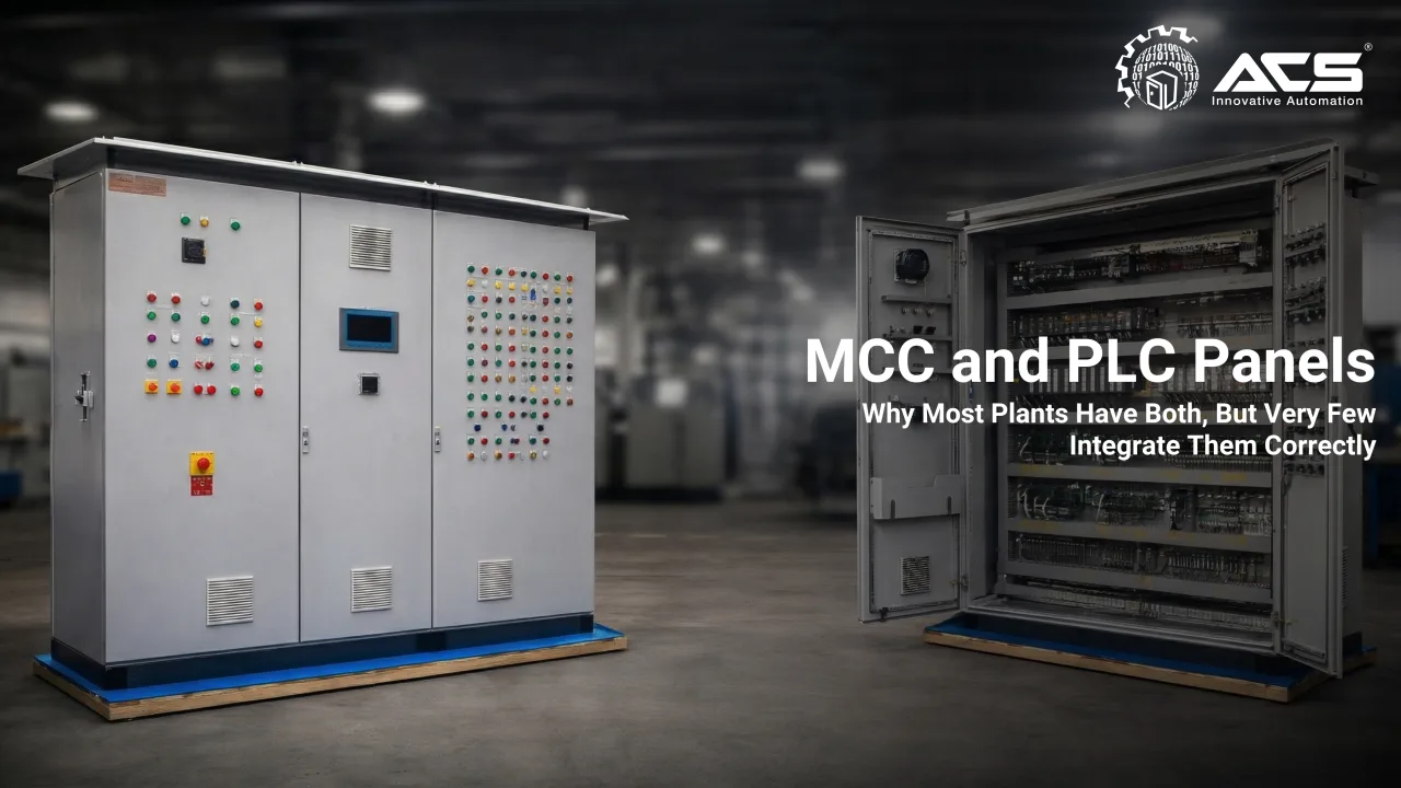
Your Motor Control Centre knows what is running. Your PLC knows what should be running. If they are not talking to each other, your automation investment is only half-realised.
Understanding the Two Panels: A Technical Primer
What is a Motor Control Centre (MCC)?
A Motor Control Centre is a centralised assembly of motor control units, combining the following functions within a single panel enclosure:
- Power distribution from the main incomer to individual motor feeders
- Motor protection via thermal overload relays, MPCB (Motor Protection Circuit Breakers), or electronic motor protection relays
- Motor starting — Direct-On-Line (DOL), Star-Delta, Soft-Starter, or VFD-based
- Isolating and switching via contactors and MCCBs
- Fault indication via pilot lamps and trip signals
MCCs operate fundamentally in the power domain. They handle kilowatts, amperes, and switching. Their purpose is to safely energise and de-energise motors, protect them from damage, and provide local isolation.
What is a PLC Control Panel?
A PLC (Programmable Logic Controller) panel operates in the control and logic domain. Its functions include:
- Processing digital and analogue inputs from field sensors (proximity switches, pressure transmitters, flow meters, thermocouples, level switches)
- Executing user-programmed logic sequences (IEC 61131-3 languages: Ladder Diagram, Function Block Diagram, Structured Text)
- Generating output commands to actuators, solenoids, motor starters, and VFDs
- Communicating with HMI displays, SCADA systems, and other PLCs via industrial networks
- Data logging, alarm management, and process historian functions
The Correct Integration Architecture
A properly integrated MCC-PLC system uses both hardwired signals and digital communication networks to create a bidirectional information and control flow between the two panels.
Layer 1: Hardwired Control Signals
Despite the rise of fieldbus communication, certain critical signals must always be hardwired for safety and reliability:
- Motor Run Command (PLC Digital Output → MCC Contactor Coil)
- Motor Running Feedback (MCC Auxiliary Contact → PLC Digital Input)
- Overload/Trip Status (MCC Overload Relay NO Contact → PLC Digital Input)
- Emergency Stop Circuit (Hardwired safety relay loop, not PLC-dependent)
These hardwired signals provide fail-safe operation. If the communication network fails, the fundamental control and protection functions remain intact.
Layer 2: Industrial Network Communication (Fieldbus/PROFINET)
For advanced monitoring and control beyond simple on/off status, modern MCC-PLC integration leverages industrial communication protocols. The most common in Siemens-based systems are:
PROFINET
- High-speed Ethernet-based communication, used with Siemens SIMOCODE pro motor management relays for detailed motor diagnostics
PROFIBUS DP
- Established fieldbus standard; widely used for MCC integration in older plant expansions
Modbus RTU/TCP
- Universal protocol; used for integrating non-Siemens drives, meters, and protection relays into Siemens PLC systems
AS-Interface (AS-i)
- Low-cost two-wire network for simple actuators and sensors at the field level
Siemens SIMOCODE pro: The Motor Management Solution
For plants requiring detailed motor intelligence within the MCC, Siemens SIMOCODE pro motor management relays represent the state of the art. SIMOCODE pro provides:
- Continuous monitoring of motor current, voltage, power factor, and active power
- Full thermal model protection — including motor starts per hour, locked rotor protection, and asymmetry detection
- Direct PROFINET or PROFIBUS integration to the PLC — all motor data available in the controller without additional wiring
- Integrated control functions — DOL, reversing, star-delta, and soft-starter control within a single device
- Predictive maintenance data — remaining thermal capacity, operating hours, number of starts
Key Benefit: With SIMOCODE pro, a plant engineer can view real-time motor current, thermal headroom, and fault history for every motor in the facility from a single SCADA screen.
This level of visibility transforms maintenance from reactive to predictive.
Interlock Design: The Logic That Protects Your Plant
Interlocking is the practice of linking the status and operation of one machine to the permissive conditions of another. It is the single most important safety and process-protection function in an integrated MCC-PLC system.
Typical interlock examples in an industrial plant:
- Conveyor sequence interlock: Downstream conveyor must be running before upstream conveyor is permitted to start (prevents material pile-up)
- Pump-tank interlock: Pump cannot start if tank level is below minimum (prevents dry-run damage)
- Cooling system interlock: The process motor cannot run if cooling water flow is below the setpoint
- Furnace-blower interlock: The gas valve cannot open unless the combustion air blower is confirmed to be running
- VFD fault interlock: Process cannot resume after a drive trip until the fault is acknowledged and cleared via SCADA
Without PLC-based interlock logic, these protections either do not exist or depend entirely on operators following manual procedures, an inherently unreliable safety layer.
Retrofit Integration: Making Legacy MCCs Smart
Full MCC replacement is not always necessary. At ACS Engitech, we have developed retrofit integration approaches for plants where the MCC hardware is relatively modern but lacks intelligent communication capability.
A typical retrofit integration project involves:
- Audit of existing MCC identifying available auxiliary contacts, terminal space, and communication-ready devices
- Installation of Siemens SIMOCODE pro units or Modbus-enabled overcurrent relays within existing MCC compartments
- Addition of a dedicated PLC panel with PROFINET/Modbus communication module
- Network cabling between the MCC and the PLC panel is typically a single Cat6 Ethernet run for PROFINET
- PLC programming for motor control logic, interlock sequences, and alarm management
- HMI/SCADA development for operator interface and motor status visualisation
The result: a legacy MCC that was built for basic motor starting becomes a fully integrated, monitored, and intelligently controlled part of the plant automation architecture without replacement.
The Business Case: Integration ROI
60-80% Reduction in time to diagnose motor faults (from physical to SCADA)
15-30% Energy savings from VFD integration with process-demand control
25-40% Reduction in unplanned motor-related downtime
100% Audit-ready motor operation logs current, starts, trips, runtime
Conclusion: Integration is Where Automation Value is Unlocked
A PLC panel and an MCC panel in the same facility, operating without integration, are two separate investments that produce less value than they should. The intelligence of the PLC is undermined by the blindness of the MCC. The protection of the MCC is undermined by the lack of process context from the PLC.
Proper integration through hardwired signals, industrial protocols, and intelligent motor management devices transforms these two panels into a single, coherent control and protection system. That is when automation delivers its full economic and operational return.
ACS Engitech designs, manufactures, and integrates MCC and PLC panels as unified systems. We are an authorised Siemens System House with in-house EPLAN engineering, panel fabrication, and site commissioning capability.
www.acsengitech.com
#MCC #PLC #SystemIntegration #PROFINET #Siemens #SIMOCODE #IndustrialAutomation #ControlPanels #ACSEngitech